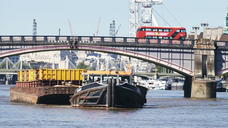
We ensure that London and the South East has a safe, clean and sustainable way of managing its recyclable and non-recyclable waste, using our unique river-based infrastructure.
Our values
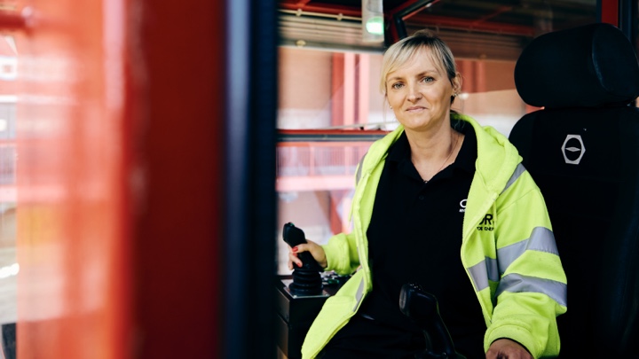
We are proud to serve a vital public function, helping to make London cleaner and safer.
Care and respect
All our employees are encouraged to promote environmental sustainability locally. We show care and respect to each other by listening and developing new ideas.
One team
We work with enthusiasm and pride, take responsibility and are the best we can possibly be through encouraging and inspiring fellow employees.
Sustainability
We educate and encourage change in ourselves, our colleagues, and our customers to promote behaviour that is aligned with our vision of sustainability.
Key facts
![]()
100,000
Vehicle journeys saved by using the River Thames to transport waste
![]()
800,000
Over 900,000 tonnes of non-recyclable waste diverted from landfill
![]()
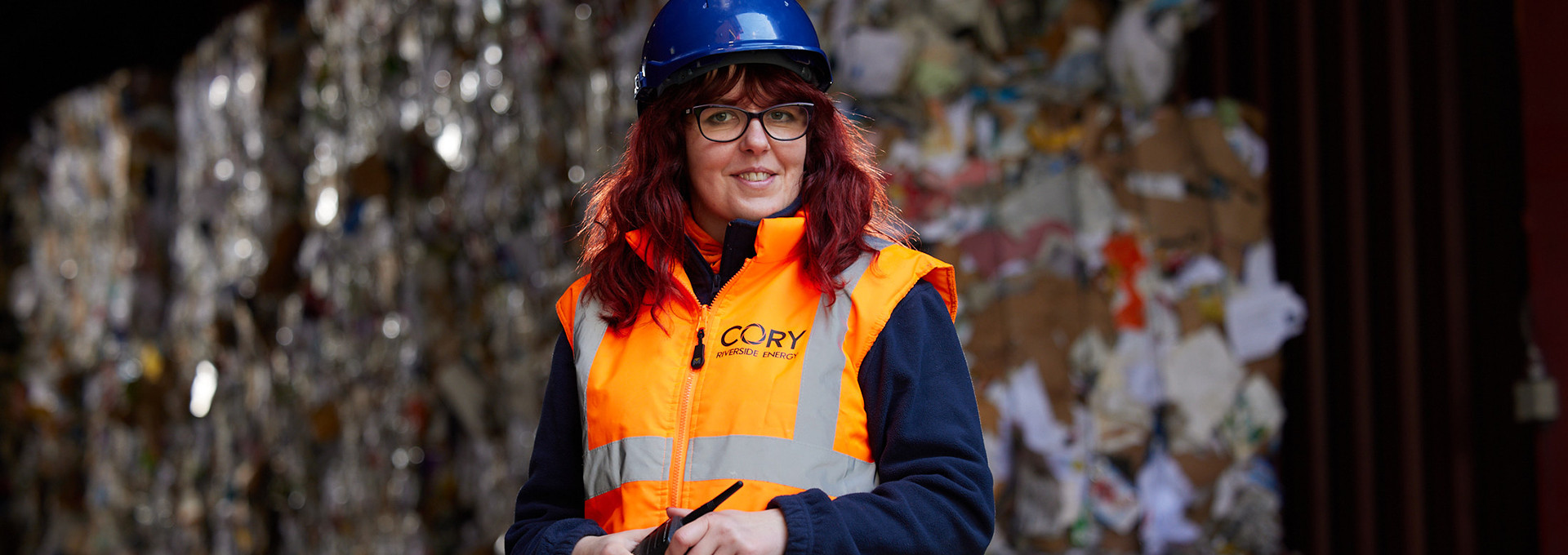
70,000
About 70,000 tonnes of recyclable waste sorted
![]()
5
Different types of plastic sorted for onwards recycling
![]()
201,000
Households powered with the electricity we generate
![]()
328,000
Tonnes of carbon saved by diverting waste from landfill
![]()
200,000
Up to 200,000 tonnes of ash recycled into roading material
![]()
10,000
Up to 10,000 tonnes of ‘air pollution control residue’ recycled to create building blocks for construction
Where we operate
We operate multiple sites from West to East London and one of the largest energy from waste facilities in the UK on the banks of the River Thames.
How our energy from waste facility works